PEGASUS AIRLINES
АНГАРЫ ТЕХНИЧЕСКОГО ОБСЛУЖИВАНИЯ И ОКРАСКИ САМОЛЁТОВ
Проектирование воздушных потоков с учётом технологии окраски самолётов
A Gerhman × Lindab Инженерное решение
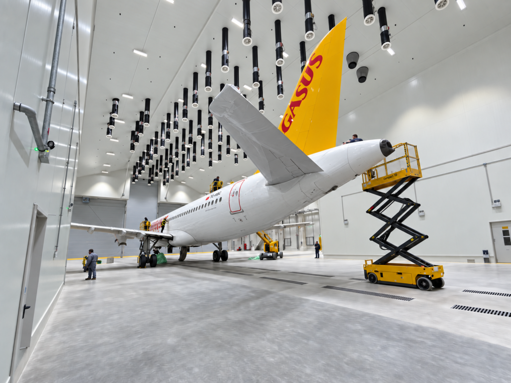
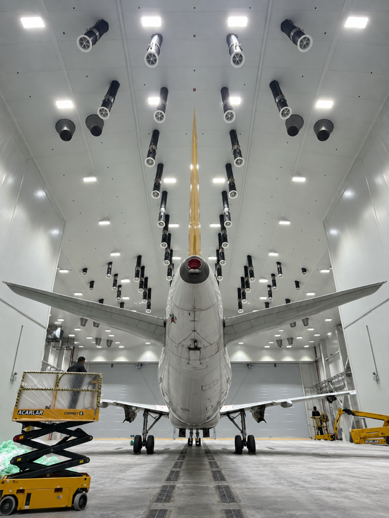
В том числе Центр обслуживания воздушных судов Pegasus Airlines в международном аэропорту Стамбула Сабиха Гёкчен Он включает в себя новые линии технического обслуживания и Aircraft Paint Hangars, разработанные для расширения возможностей авиакомпании по техническому обслуживанию самолетов.
Предприятие обеспечивает возможность одновременного технического обслуживания для Четыре узкофюзеляжных самолетаВ то время как выделенный ангар краски вмещает один узкофюзеляжный самолет для подготовки поверхности и выполнения операций по окраске.
Ангары для окраски воздушных судов требуют подхода к вентиляции, значительно отличающегося от обычных систем комфорта HVAC.Система воздухораспределение должна поддерживать требуемые скорость воздуха и условия окружающей среды вокруг большого и аэродинамически сложного самолета при поддержке контролируемого транспорта краски, паров растворителей и летучих органических соединений (ЛОС) к системе экстракции.
По этой причине вентиляция считается неотъемлемой частью процесса окраски самолета, а не просто функцией здания HVAC.
Gerhman в сотрудничестве со своим стратегическим партнером Lindab По согласованию с механическим субподрядчиком Birleşim Mühendislik, разработанное решение воздухораспределение на этапе проектирования Выбор продукции, системные расчеты, анализ CFD, оптимизация воздушного потока и ввод в эксплуатацию.
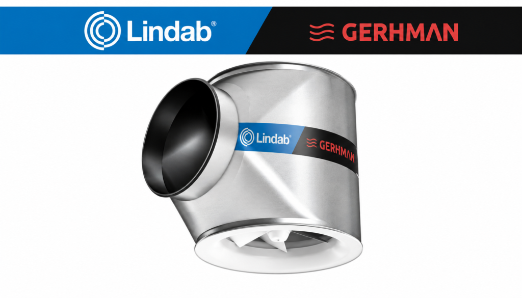
Система воздухораспределение была реализована с использованием Малотурбулентные диффузоры вытесняющей вентиляции Lindab RCW, отобранные и сконфигурированные в соответствии со специфическими аэродинамическими и эксплуатационными требованиями покрасочного ангара самолета.
Инженерный вызов
Реконструкция самолета состоит из нескольких различных процессов:
Стриптиз краски → Очистка → Подготовка поверхности → Приминг → Заключительная живопись
Эти операции не обязательно требуют одинаковых условий вентиляции.Необходимые скорости поверхности, загрязняющие нагрузки и активные рабочие зоны изменяются на протяжении всего процесса окраски.
Геометрия самолета создает дополнительную инженерную задачу. фюзеляж, крылья, двигатели, горизонтальные стабилизаторы и вертикальный хвост Действуют как большие аэродинамические препятствия внутри ангара.
Их взаимодействие с потоком воздуха может создавать:
Низкоскоростные области · Аэродинамические теневые зоны · Местная рециркуляция · Неоднородные скорости поверхности
Простое увеличение общей скорости вентиляции не обязательно устраняет эти условия.
Таким образом, инженерная задача состояла в том, чтобы установить требуемая скорость воздушного потока и направление вокруг активных поверхностей самолета;Сведение к минимуму ненужного потока воздуха в районы, где не происходит никакого активного процесса.
Инженерный дизайн и выбор продукта
Gerhman разработал систему, используя Инженерный расчет и программное обеспечение для выбора продукта.
В процессе проектирования были оценены основные аэродинамические и тепловые параметры, влияющие на воздухораспределение:
Скорость воздушного потока · Поверхность скорость воздуха · Скорость разряда · потеря давления · Расстояние разбрасывания · Глубина проникновения в самолет · Направление разряда · Температура подачи воздуха · Операционная зона
Различные сценарии эксплуатации оценивались в соответствии с отдельными этапами процесса окраски самолета.
Такой подход позволил проектировать систему воздухораспределение в соответствии с фактическими требованиями процесса, а не определять размер ангара вокруг одного максимального рабочего состояния.
CFD Анализ воздушного потока
По предварительным инженерным расчетам, Вычислительная динамика жидкости (CFD) Анализ использовался для оценки и оптимизации предлагаемой концепции воздушного потока до ее реализации.
В CFD исследованиях анализировалось взаимодействие между:
Подача воздушных потоков + Lindab RCW Диффузоры + Геометрия летательных аппаратов + Зоны процессов + Система экстракции
Моделирование использовалось для оценки:
- Распределение скорость воздуха вокруг самолета,
- равномерность поверхностного воздушного потока,
- направление воздушного потока и проникновение струй,
- потенциальные зоны низкой скорости и рециркуляции;
- поведение воздушного потока вокруг фюзеляжа, крыльев и хвоста;
- взаимодействие между притоком и вытяжкой,
- Альтернативные зональные сценарии.
Таким образом, CFD служил в качестве Инженерное проектирование и инструмент проверки- возможность анализа альтернативных конфигураций до внедрения окончательной системы;
Это было особенно важно, потому что обычные расчеты изменения воздуха и выбор диффузора на основе каталога сами по себе не могут полностью представлять сложные трехмерные модели воздушного потока, созданные вокруг самолета.
воздухораспределение Продукция: Lindab RCW
Окончательное решение воздухораспределение было реализовано с использованием Малотурбулентные диффузоры вытесняющей вентиляции Lindab RCW.
Подразделения RCW были выбраны за их способность обеспечивать аэродинамические характеристики, требуемые в процессе окраски самолета:
Низкая турбулентность вытесняет поток воздуха
Регулируемое направление подачи воздуха
Электрически контролируемая глубина реактивного проникновения
Низкий потеря давления
Стабильная работа в условиях нагрева и охлаждения
Эти характеристики позволили адаптировать модель воздухораспределение в соответствии с Геометрия самолета, зона активного процесса и требуемая поверхность скорость воздуха.
Низкая турбулентность воздухораспределение
Чрезмерное турбулентное смешивание нежелательно в приложениях окраски самолетов, потому что оно может перераспределять избыточное распыление и загрязняющие вещества в воздухе и генерировать местную рециркуляции вокруг поверхностей самолета.
Lindab единиц RCW вводят кондиционированный воздух с использованием принцип вытеснения с низкой турбулентностьюсоздание контролируемого поля воздушного потока через активную рабочую зону.
Конструкция поддерживает определенный путь воздушного потока со стороны подачи, через рабочую зону и в направлении системы извлечения.
Таким образом, инженерная цель состоит не только в обеспечении необходимого общего потока воздуха, но и в установлении правильного воздушного потока. Распределение скорости и направление воздушного потока на поверхности самолета.
Это поддерживает контролируемую транспортировку избыточного спрея, паров растворителей и ЛОС в систему экстракции при ограничении ненужной дисперсии в ангаре.
Регулируемое воздушное направление и реактивное проникновение
Различные части самолета требуют различных траекторий воздушного потока и расстояний проникновения.
Потребность в воздушном потоке вокруг фюзеляжа, например, отличается от потребности вокруг крыльев, хвостовой части или нижних поверхностей самолета.
Lindab единиц RCW включают в себя электрический привод для регулировки характеристик разряда и глубины проникновения струи.
Это позволяет адаптировать структуру воздушного потока в соответствии с активной рабочей зоной.
Там, где требуется большее проникновение, характеристики разряда могут быть соответствующим образом отрегулированы, а там, где активный процесс находится ближе к зоне подачи, ненужное проникновение может быть уменьшено.
Эта способность была важным элементом в разработке стратегии зональной вентиляции на основе процесса.
Процессно-ориентированный зональный контроль
Основная оптимизация системы была достигнута заменой первоначальной. Концепция полноразмерной вентиляции с зонированием на основе процессов.
Вместо того, чтобы рассматривать весь ангар как единую зону вентиляции, работающую непрерывно в пиковых условиях, самолет и окружающие рабочие зоны были разделены на: Функциональные зоны процессов.
Таким образом, система могла бы обеспечить требуемое:
Скорость воздушного потока + Скорость поверхности + Направление воздушного потока + Проникновение джета
В соответствии с активной зоной самолета и процессом окраски.
Кондиционированный воздух направлялся туда, где он действительно требовался, а не поддерживал полный ангар в максимальном конструктивном состоянии.
Этот инженерный подход привел примерно к следующему:
СОКРАЩЕНИЕ НА 64%
ТРЕБУЕМОЙ ПРОИЗВОДИТЕЛЬНОСТИ ПО ВОЗДУХУ
По сравнению с первоначальной полноразмерной концепцией вентиляции.
Сокращение было достигнуто за счет Лучшее использование и распределение кондиционированного воздухаВместо того, чтобы скомпрометировать требуемые условия вентиляции.
Вклад в энергоэффективность
В том числе Фигура 64% представляет собой сокращение требуемой проектной пропускной способности воздушного потока., а не сокращение общего энергопотребления на 64%.
Тем не менее, снижение требуемой пропускной способности воздушного потока оказывает значительное влияние на энергопотребление всей системы вентиляции.
Воздух в процессе лакокрасочного процесса самолета обычно проходит через несколько энергоемких этапов:
Фильтрация → Вентиляторный транспорт → Отопление / охлаждение → Контроль влажности → Снабжение → Добыча
Таким образом, сокращение ненужного воздушного потока способствует снижению:
Энергопотребление вентиляторов
Отопление
Охлаждающая нагрузка
Спрос на увлажнение и осушение
Общая потребность в обработке воздуха
В том числе Низкие потеря давления диффузоров Lindab RCW обеспечивает дополнительный вклад, минимизируя потери давления в системе подачи-воздуха.
Таким образом, оптимизированная конструкция уменьшает количество воздуха, которое необходимо постоянно транспортировать и кондиционировать, внося существенный вклад в общее качество воздуха. энергоэффективность и эксплуатационные расходы на жизненный цикл Средства.
Температура и условия влажности
Температура и относительная влажность являются важными параметрами процесса окраски воздушных судов, поскольку они влияют на качество воздуха. нанесение краски, испарение растворителя, поведение покрытия, отверждение и качество конечной поверхности.
Lindab RCW предназначен для поддержания своих предполагаемых характеристик воздухораспределение с перепадами температур от подачи к возврату до:
Охлаждение: ΔT = –5 K
Отопление: ΔT = +8 K
Операция по отоплению: ΔT = +10 K
Температура и влажность контролируются соответствующей системой обработки воздуха, в то время как блоки RCW распределяют кондиционированный воздух в соответствии с требуемыми аэродинамическими условиями в зоне процесса.
Согласование притока и вытяжки
Производительность системы вентиляции «краска-ангар» самолета не может быть оценена независимо от терминалов подачи воздуха.
Поле конечного потока воздуха определяется взаимодействием между:
Система снабжения + Диффузоры RCW + Геометрия самолета + Система экстракции + Стратегия управления
По этой причине системы снабжения и добычи рассматривались как часть одной и той же концепции воздушного потока.
Цель состояла в том, чтобы поддерживать предполагаемый путь воздушного потока через рабочую зону и к точкам извлечения при минимизации областей низкой скорости и рециркуляции вокруг самолета.
Этот системный подход был включен как в анализ CFD, так и в окончательную оптимизацию воздушного потока.
От проектирования до ввода в эксплуатацию
Gerhman были задействованы в разработке и внедрении системы воздухораспределение.
Инженерный рабочий процесс сопровождался непрерывным процессом проектирования и проверки:
Требования к процессу
→ Инженерные расчеты и выбор
→ Lindab RCW конфигурация
→ CFD Анализ
→ Оптимизация зонального воздушного потока
→ Осуществление системы
→ Тестирование и ввод в эксплуатацию
Эта методология была важна, потому что фактическая производительность ангара краски самолета не может быть определена только из отдельных данных каталога диффузора.
Вся система должна быть оценена с учетом взаимодействия между Система воздухораспределение, геометрия самолета, устройство извлечения и условия эксплуатации.
Инженерный результат
Через Gerhman - Lindab сотрудничествоПервоначальная концепция полноразмерной вентиляции была переработана с учетом фактических аэродинамических и технологических требований к окраске самолетов.
Gerhman инженерных расчетов и средств выбора продукции, в сочетании с Анализ CFD и диффузоры с низкой турбулентностью Lindab RCW, позволял направлять кондиционированный воздух в требуемые авиационные зоны с контролируемой скоростью, направлением и проникновением.
Полученный дизайн достиг приблизительно:
64% Сокращение требуемой пропускной способности воздушного потока
Сохранение требуемой стратегии воздушного потока на основе процесса.
Сокращение спроса на кондиционированный воздух также вносит значительный вклад в снижение спроса. вентилятор, отопление, охлаждение и требования к энергии для контроля влажности.
Проект демонстрирует важный принцип технологической вентиляции:
Эффективность системы зависит не только от количества подаваемого воздуха, но и от того, насколько эффективно этот воздух распределяется в требуемой технологической зоне.
Основные моменты проекта
Проект: Pegasus Airlines — ангары технического обслуживания и окраски самолётов
Местонахождение: Международный аэропорт Стамбула Sabiha Gökçen, Türkiye
Клиент: Авиакомпания Pegasus
Механический субподрядчик: Birleşim Mühendislik
Применение: Техническое обслуживание самолётов / Окраска самолётов / MRO
Вместимость обслуживания: 4 узкофюзеляжных самолёта
Вместимость окрасочного ангара: 1 узкофюзеляжный самолёт
Инженерное сотрудничество: Gerhman × Lindab
Используемый продукт: Lindab RCW — малотурбулентный диффузор вытесняющей вентиляции
Методология проектирования: Инженерные расчеты · Программное обеспечение для выбора продукта · Анализ CFD · Процессное зонирование
Стратегия воздушного потока: Низкотурбулентный смещающий поток · регулируемое направление воздуха · переменное проникновение джета · зональный контроль
Ключевые инженерные результаты: 64% Сокращение требуемой пропускной способности воздушного потока
Энергетический эффект: Снижение спроса на кондиционированный воздух с более низкими требованиями к вентиляторам, отоплению, охлаждению и контролю влажности
Gerhman Область применения: Инженерное проектирование · Выбор продукции · Анализ CFD · Оптимизация воздушного потока · Интеграция системы · Тестирование и ввод в эксплуатацию